

Copyright © 2011-26 Helical Pile World, LLC. All Rights Reserved.
Home | Engineers | Manufacturers | Installation Contractors | News | Contact Us


What's Wrong with This Helical Foundation?
Presented at the DFI Seminar November 11, 2006 Newark, NJ
by contributors Donald E. Bobbitt, P.E., FASCE, Staff Engineer, Midwest Diversified Technologies
and Wayne Rogers, P.E., President, Energy Structures

Helical piles and foundations provide a great solution for some design challenges but sometime present challenges of their own. These challenges are in the form available sizes, installing contractor or of construction nature. This paper presents actual problems encountered in the use of helical products as foundations and tiebacks in a variety of applications. The solutions proposed herein have been used to prevent or resolve these problems and drawbacks in North America and internationally.
Introduction
Helical screw anchor or foundations have been in use for nearly two centuries of known history. Likely as not, some crude screw plate device was used to anchor animals and tents since the nomads wander the various continents. While not a new technology the more recent extensions of new uses for the helical foundation has introduced new challenges and drawbacks. The drawbacks and challenges can be separated into several broad areas of concern: first, the availability of the foundation device; secondly the proper means (equipment and personnel) to install the foundations; thirdly, the construction or installation of the helical foundation and finally the failure of the foundation to perform its intended function.
The “availability" issue is beyond the scope of this paper and is often negated by having a reliable supplier. The remaining three drawbacks or challenges will be treated in this presentation. While these solutions are from the experience of the authors in the use of helical foundation domestically and throughout the world, it is not an exhaustive recitation of their combined 70+ years of experience or the only possible solutions. We hope this listing will start a dialog within the practice that will show the helical products to be user friendly and debunk or demystify this very usable foundation type for the greater good of all practitioners. Sharing knowledge will increase the use of the helical foundation and we will all benefit.
We won the bid!
This is great news and the required submittals are in, mobilization is eminent; now what? Certainly your estimator thought through the process and put a number to the project but is your crew ready? Proper preparation is fundament to successful contracting. Proper tooling, personnel trained in the safe installation techniques of installing and testing helical foundations and adequate preparation is a must to be a profitable contractor. A checklist in the appendix may be helpful in this regard. The design professionals also need to know what should be done by the contractor to prepare so they better respond to field situations and problems.
A brief overview of the preparation process is included herein. While not extensive these are necessary minimum steps one must take to prepare for execution of the contract. The following office procedures assume all the contract documents, including the geotechnical report have been read and understood.
A. Mobile equipment- is the carrier properly sized to access the site, including physical size, ground pressure, head room, reach and stability on the site? The drive head or hydraulically driven gear box should have at least 50% greater torque capacity than the mechanical limit of the product to be installed and should have an accurate method of determining installation torque.
B. Personnel-The crew size depends on the type of work they are to perform. For the typical foundation project, a three man crew is an adequate for most foundation project. This includes the lead man or foreman, an operator and a groundman. All should be trained in safety and correct installation procedures. Additionally, the foreman is responsible for the keeping of adequate installation records and should be able to articulate any field problems encountered to headquarters for prompt resolution.
C. Know the soil- What has been your local experience in that soil profile or what is the regional or local geology. At least review the borings with respect to where the crew plans to start. It is often prudent to start near a boring so one can check the “expected performance” to hold with actual performance. This will allow early warning of potential problems such as wrong depth estimated and other installation challenges. (In the absences of boring, send down a single helix test probe, one having a large diameter helix is better to determine soil stratum locations, and record depth and torque each foot of penetration below the first five feet). This can provide some guidance in selecting the final helical foundation configuration.
The mobilization process is completed and the production or installation begins. If adequate preparation has been completed the startup process should have a fairly short learning curve and a good production rate will be quickly established. Production is proceeding well.
Installation of the helical foundations moves along well until a problem is encountered. The problem may be product, installation or performance as stated above in the introduction. Each will be treated separately below. These categories or functions are product, installation and performance with the majority of the field problems arise in the installation function. Never-the-less, each aspect of the application of helical foundations needs consideration.
1. Product problems- The construction phase of the helical foundation applies loads that are the most difficult for the product to withstand. The required installing torque may be approaching their published limits to get the helical bearing plate to the desired bearing stratum. Proper alignment so as not to introduce bending on the shaft is important. The combine stresses, bending and torsional, can cause shaft to fail prematurely. This can also cause the coupling to fail prematurely. Excess down pressure and misalignment (drive head not co-axial with anchor shaft) will cause premature failure due to the higher combined stresses. The obvious answer to this is to align the drive motor co-axial with the shaft and apply just enough down pressure to follow the top end of the helical foundation. Using a tubular shaft anchor will also reduce this potential failure.
Hitting boulders and cobbles may fold the leading edge of the helix causing the rate of penetration, the installing torque and the capacity to be greatly reduced. The various manufacturers can provide thicker and higher strength helices for rocky ground by using thicker and /or higher strength helices will help prevent this problem. As a field expedient the leading edge may be straighten mechanically or the folded up portion of the helix can be remove with an abrasive saw. If a torch is used, keep the cut ½” away from the weld.
The fasteners could break under load. The manufacturers supply the proper grade of bolt for their produce. If you require more bolts because some have been lost, obtain them from the manufacturer or be sure to use the grade required in their specification. A higher grade bolt may actually be more brittle than the OEM bolt.
While the rotation of the shaft in the drive tool is a tooling problem will be discussed further below. Preliminarily however, the subject is included briefly here as the tools are part of the “Products” purchased. Always use the proper drive size tool, in good condition, and pin the anchor shaft to the drive tool so it won’t slip out causing a dangerous condition for the groundman. Drive tools or sockets that are so rounded out and worn that the anchor shaft fits loosely into are a hazard.
Shaft fails prematurely- The manufacturers’ rate the strength of the shaft based on pure torsion applied in a laboratory environment. The ratings are probably good for the typical installation but if bending is introduced due to the location or reach of the installing machine, failure from combined stresses may result. The fracture surface may be correctly identified by the spiral form of the break, since a pure torsion break of a ductile material is a smooth break perpendicular to the axis of the shaft.
2. Installation matters-Thrust is developed by the action of the helical screw foundation threading its way into the ground. The installing equipment cannot hold it back and the equipment has been damaged when the proper down pressure or following motion was not applied. On the other hand, “down pressure” may be developed with the installing equipment by carefully applying a compressive load to the top of the extension. Both help cause the foundation to penetrate the ground. It should be also noted that fowling of the helices with trash or Geofabrics can reduce the rate of penetration and torque due to the “auguring” action of the lead section.
The helical foundation is usually installed with a right turning motion (exception for the left turning moment for under water installations), typically produced by a hydraulically driven gearbox or “drive motor”, and requires constant torsional force on the order of thousands of foot pounds. There are a dozen or so high capacity drive motor manufacturers. A few are direct drive hydraulic piston pumps but the majority is high capacity hydraulic gear motor driving a heavy-duty gearbox. It doesn’t readily matter who makes the drive motor so long as the maximum hydraulic pressure is known so the seals are not blown on the gear box, which typically happens after the seals of the drive motor are blown due to over-pressuring the drive motor. Know the maximum pressure the motor to which the rated. Excessive backpressure (which on backhoes may be designed to 600-800 psi), can occur in the return line and filter, is the most common reason for blowing seals in the hydraulic motor. One preventative measure the mechanic can do is to vent the motor case. Motor seals can be repaired; prevention is easier, just vent the case. The appendix shows a drive motor case drain sketch. It is also recommended to adjust the relief valve on the motor so that the maximum pressure will not exceed the ultimate capacity of the digger motor or drill string.
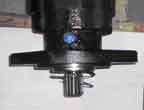
Figure 1 - Blown motor seal
Note the plastic plug which is immediately above the flange is the case drain. A case drain, having a 10 psi check valve in the line would have prevented this failure had it been installed in this opening. Operating a drive motor below water can also cause pressure in the opposite direction (i.e. back pressure in the return line). However, they have been successfully deployed to depths as great as 285 feet without failure.
Tooling problems - While this subject has been discussed briefly above it bears treating again. One should use the recommended drive tooling supplied by the manufacturer and follow their safety instructions including replacement of worn equipment. These safety procedures should be part of the weekly safety meeting. Worn and improper tooling can contribute to low production and possibly a dangerous work situation. Modifications of the manufacturers’ tooling void the warrantee and transfer all liability to your company. The writers are aware of serious injuries and one death arising from improper tooling being used as field expedient. All rotating equipment has inherent dangers associated with them and can be very unforgiving if carelessness is permitted.
The drive motor or “digger head” has been discussed above. The torque indicator is ancillary to the digger head and should be in the drive tool string if mechanical or should measure the hydraulic gradient across the motor if hydraulic. Since many installers blindly accept the relationship between torque and capacity, it behooves them to have a verifiably accurate torque indictor. Hydraulic torque indicators typically use a Bourdon gauge movement to indicate the pressure. Such gauges can be overstress and damaged requiring they be replaced. Hydraulic indicators should be recalibrated from time to time as it possible to damage the helical product due to unreliable torque indicator being used as a drive criterion.
Also torque indicators should be able to monitor torque continuously. Break-away mechanical or pressure relief systems are not recommended unless constant speed and down pressure are maintained because an increase in either of these aspect may cause a premature break-away or indication of installing torque.
When applying torque as a means of predicting capacity, it is important to install the anchor at the speed (rpm) recommended by the manufacturer. Excessive rotational speed may result in unrealistically high torques.
When the torque indicator becomes inoperative or in the absence of a torque indicator, some contractors will rely on system pressure or twist of the steel shaft to install helical anchors. (System pressure is not a good indication of installing torque and will not be addressed here). Shaft twist was the practice for the years preceding the mechanical torque indicator. However, it can result in excess anchor capacity (typically means extra depth and expense), unexpected shaft failure and unreliable capacity implied. If a torque indicator is not used, it would be prudent to test a sufficient number of anchors, say 20-30% of the total number in the case of tension anchors, which are easy and fast to test and typically have a lower factor of safety specified; or 2-3% of the total number in the case of compression piers. Remember, installing torque criteria is site specific.
A not so common situation may arise in the case of tension anchors, such as tiebacks for sea wall and deep excavation bracing where the installation angle of the tieback is fairly flat. This can give rise to the lead helix hitting a hard subsurface layer and then continue to walk along the interface of the layer, never increasing in torque as one would normally expect. This is sometimes evident on the face of the wall as the outer end of the anchor will attempt to move lower down the wall. Extract the tieback and increase the length of the stinger (pilot point) or increase the angle and re-install the tieback in a new location.
The helical foundation may be installed in the wrong location or it has to be moved because of an obstruction: what are the possible moves one can make? Obviously this may be a function of the load requirements but as far as the helical foundation is concerned one should move it far enough away so the helical lead will not try to “drift “ into it former location during reinstallation. This generally requires a move of 3’ or more or an angle change, if permissible, of 15 degrees or more.
Sometimes the helical foundation will stop penetrating into the soil at the normal rate or completely “spin out”, i.e. turn without advancing. This may be due to several causes; first, the foundation shaft having a solid square cross-section has stopped advancing because the lead end has encountered a stratum so hard that the lower helix can not develop enough thrust to force the tip into the stratum. In that case, remove the foundation and shorten the pilot point and modify/sharpen the helices and then reinstall using the maximum down pressure that can be put on the shaft at the depth the foundation stalled previously. Care should be exercise as not to cause the shaft to buckle.
If the foundation shaft is circular in cross-section, there may be two reasons for the excessive torque: first, inadequate thrust as mention above and secondly because the shaft is “using up” so much torque in skin friction that the thrust developed by the leading helices cannot overcome the skin friction. In the latter case, extreme down pressure from installing machine may overcome this problem. Adding helices along the shaft or reducing the diameter of the shaft of the lead and some of the extensions is also effective. By way of reference, the authors have found the average maximum length of an 8” diameter shaft foundation, without intermediate helices, is on the order of 40’ in soft to medium soil. This is due to the lead section thrust being overcome by the friction along the shaft. In the very soft soils and peat deposits, the average length can be much longer
The prescribed installation torque is not being achieved during installation to the predetermined depth will cause panic in some camps. If one has a good reason to believe the helices are in the prescribed bearing strata, test the foundation before driving the foundation much deeper. A quick tension test will give some indication of capacity and they are easy to perform. Recall that torque is site specific and to blindly use the default value will typically yield a conservative capacity but perhaps an overly conservative value that is expense to achieve.
Granular material where the water table fluctuates, such as tidal areas, or will rise it the future as a result of some natural or man made site change, will affect the ultimate capacity of the helical foundation. The capacity of the bearing plate(s) in sand is a direct relationship to the effective overburden pressure. The rising water table will reduce the capacity of the plate as the buoyancy of the water reduces the overburden pressure. In this case, the original calculations should consider the potential long-term influence of the water table and the reduction in capacity.
Sand below the water table and below the floor of the sea can cause an increase in the installing torque require. The helical foundations may “augur”, i.e. turn without advancing the normal distance, into loose saturate sand in some cases causing it to densify and actually increase its capacity above what is indicated using the default values of torque to capacity ratios. This is an anomaly and can be detected by full scale testing. Once again; the torque to capacity relationship is site specific.
When a helical foundation is installed into a soil profile that has a very soft to soft strata near the surface buckling may occur under load. This can be prevented by reducing the axial load to 10 kips or sleeving the shaft through the soft layer or the use of the so-called Helical Pulldown® Micropile. This is a patented method, exclusively licensed to Chance. However, a pipe sleeve may be driven down around the shaft, through the soft strata thereby reinforcing the slender shaft. Another approach is the Composite Helical Pipe Pile ® (CHPP ®) which includes tubular pipe sections (usually 8.625” OD but can be larger). The bottom section of the CHPP connects directly to standard square shaft or HS helical lead sections. The pipe sections are configured so that their inside remains open for concrete, and rebar, if required. Helixes may also be welded to the pipe sections if/as required. As with the Helical Pulldown® Micropile, this method is patented.
Affect of grain size and angularity in non-cohesive soils is to increase capacity with increasing grain size and angularity. Since this angularity information is seldom provided to the designer, he may get a surprising call from the field. One possible solution is to have the crew perform a “quick” tension test and act accordingly per the test results. Typically the tension tests prove that higher torques actually produce higher capacity screw foundations. If the helices have a shallow embedment into the dense layer, the tension test may fail the anchor but in compression, it will perform well. The point being that if the helical foundation is in the adequate bearing material, without regard to the torque, testing it in tension or compression may prove the foundation to be a good.
Installing helical piles through ice for structures such as utilidors and for foundations in permafrost also present a challenge. Some of the Native American villages in Alaska have their domestic water and sewer running inside insulated utilidors that are elevated above the ground surface. They are often constructed in the winter through thick layers of frozen ground and ice. Pre-drilling the hole with an ice bit having a diameter larger than the shaft and/or cutting of the pilot point and sharpening the helices significantly improved the rate of installation.
Permafrost is not the same everywhere; warm fine grain and cold coarse grain permafrost behave differently. The results of testing in June, 1985 showed that installing helical anchors in some type’s permafrost (such as that occurring in Prudhoe Bay, Alaska) can be extremely difficult if not impossible.
3. Performance Problems
The slender shaft of the foundation can buckle under load as indicated by the sudden reduction in capacity and/or a constant rate of strain at a constant applied stress, can occur in soft or loose soils. The authors’ experience indicates this can occur in soft or loose soil when using the inch and one half square shaft foundation between twenty and twenty-five kips. (While smaller shafts are available, it is not recommended they be used in a compression application). Should this occur, several solutions are given above. The use of tubular shaft foundations is recommended if none of the solutions proposed above are available.
When deep excavations are made adjacent to an existing building, the existing foundations are underpinned. The underpinning must be supported; which is the first principle of underpinning as advocated by White [i], to prevent catastrophic failure of the existing structure. The design of the tiebacks and wall is beyond the scope of this paper and is mentioned here as a precautionary note. Get a structural engineer practiced in this specialty to design adequate retaining tiebacks and wall.
Corrosion is a subject on which some suppliers and consultants wax elegant. The authors experience indicates it is generally of little concern when helical foundations are installed in undisturbed earth. The work done by Romanoff[ii] shows this to be the case. The general guideline that is often used in all but institutional structures is if the resistivity is greater than 1000 ohm-cms. and the pH is between 4.5 and 9 the foundations should have a service life in excess of the 70 years. It is prudent to grout the inside of tubular shafts if in a corrosive environment. The subject of corrosion is treated conservatively by some of the manufacturers’ literature, as indicated earlier.
If the helical foundation doesn’t pass foundation test, install deeper and test again. Should the foundation be removed and replace with a bigger foundation it is recommended that the installation site be moved, as the new foundation may not penetrate deep enough past the original test depth to have a legitimate test. If it is decided that the tested foundation is to be used, derate the foundation to one half the load at which the deformation criteria was met.
The performance of the helical foundations in seismic events has been reported to be very good, often out performing the adjacent conventional foundations. This is a difficult problem to quantify and is treated here as reported anecdotally. They have been in service in civil works for over 20 years in seismic prone areas and have experienced earthquakes over R-7 with good performance. These structures include retaining walls, commercial, government and residential buildings. There are no reported failures of structures supported on helical foundations due to seismic events.
Cost can become prohibitive if the site conditions are not well known and high capacity foundations are required. One needs to evaluate the total cost, including time, material, site disruption, and money saved by possibly shortening the construction time. It has been often reported that the saving produced by not loosing productive time at the facility where the work was done more than justified the use of helical piers. Probably every helical foundation contractor can tell you a story about this very situation.
Long-term performance in clay is an often-posed question. This is a legitimate concern as strain soften can occur, particularly in the tension application. Strain softening may occur when a tension anchor is loaded in a long-term situation at or near its ultimate capacity because the tension loading causes a negative pore pressure adjacent to the helical plate. This negative pore pressure is satisfied or overcome by pore water flowing to the helix site. In time, the water can cause a softening of the adjacent soil permitting the soil to flow around the helical plate in a “deep local shear” mode. Strain softening occurring in the normally to slightly over consolidated fine grain soils (OCR=3 to 4) has not been observed to the authors’ knowledge. Unreported testing[iii] by the A.B. Chance Company actually showed a slight gain in the long term ultimate capacity verses the ultimate capacity found by “quick testing” method in the slightly over consolidated soil. However, a test by Northern States Power[iv] found about a ten percent reduction in capacity of tension anchors that had been loaded long term on an angle structure of an EHV transmission line.
Installation below water surface can increase the required installing torque in the case of coarse grain, angular sand. The required installation torque may be so high that the helical foundation shaft may be driven beyond its mechanical limit, causing breakage of the shaft. Reducing the size of the helices or increase the shaft size, hence its strength, are the two methods that are acceptable. Pre-drilling the hard soil is generally not an option as it will reduce the capacity if drilled too deep.
Conclusion
The helical foundation, used in tension and/or compression has been in use for many years. It has been subject of curiosity and research in the past but only recently has been widely used in the construction market. The authors believe this is due to two factors; first the world of academia has not embraced the concept to the extent it recognized in the text books and covered on the undergraduate level and secondly, the practitioner view it as too “complicated” to solve the occasional field problem and they have to rely on the contractor to work around any field problem. The applications are myriad and common sense approaches to solving most difficulties are readily achieved. The helical foundation is here to stay and it behooves the practitioner and constructors to explore the use of helical products because the use of the helical foundation for compression and tension applications expands daily.
[i] White, Lazarus-Underpinning, Columbia Press, NY,NY,1906
[ii] Corrosion of Steel Piling in Soil, National Bureau of Standards Monograph # 58, 1962
[iii] Testing by Chance (Bobbitt, 1974) for internal use only
[iv] Private conversations between Bobbitt and Earl Weisner - NSP transmission engineer, 1993