

Copyright © 2011-26 Helical Pile World, LLC. All Rights Reserved.
Home | Engineers | Manufacturers | Installation Contractors | News | Contact Us


Production & Field Control for Helical Pile Installation
by contributing author Donald Bobbitt, P.E.
HPW Archive 2006

This paper discusses the relationship of the installing torque and holding capacity of helical foundations and tiebacks. A brief background and description of the genesis to the torque to capacity relationship and the logic behind this concept is discussed. Various theories and results are also presented and recommendations based on empirical results are included.
Helical Foundation and Tieback
The helical foundation, whether in compression or tension have the same basic form and function. They consist of a helical plate installed into the bearing stratum deep enough to behave like a deep foundation in tension or compression Researchers have found differing depths of embedment depending on the soil, but an average or a usable value is 5 diameters is the widely accepted depth. Intuitively, it is apparent that in very soft clays the plate does not need to be very deep whereas in hard dry soil, 5 diameters is not enough depth to develop theoretical shear behavior of a deep foundation. The published minimum depth is 3 diameters for the desired behavior but research in very soft clays indicates a depth of less than 3 will fully develop the limiting conditions for the buried plate.
Components
The basic components of the helical foundations are the same, regardless of the manufacturer. They consist of three elements welded or fixed together to act as a unit in the intended application. The uppermost end of the helical foundation is the termination. It is designed and fabricated to collect the applied load from the loaded structural member. It may be as simple as a formed eye or treaded rod to as complex as a weldment to accept tension and compression at a grade beam. The intermediate component of the foundation is the shaft, which has a two-fold function. The shaft is used to transmit the installing torque to the helical plate during installation and when in service, to transmit the imposed load to the bearing plate of the foundation The lower end is a helical shaped plate that transfers the load to the bearing stratum in a manner consistent with the physical properties of the stratum. The helical form of the plate is critical and the more nearly the plate conforms to a true helix, the less soil disturbance it will cause as it passes through the soil. Ideally the plate will pass through the soil by causing the soil particles in front of the cutting edge to move or displace upward momentarily as the helical plate passes through it and then return to its original position after the plate passes by. While the installation does disturb the soil, one can not readily measure the affects of the installation on the gross soil properties in all but the soft to very soft clays.
The plates function as bearing elements, in tension or compression, whichever the application. Helically formed plates provide the bearing area under load. During installation they also provide the thrust or downward force that keeps the foundation advancing into the soil. Downward force applied at the upper end of the foundation during installation may be of benefit in soft soils or when very large helices or large diameter shafts are being use for the foundation. However, excessive downward force or rotational speed on the driven end can increase the apparent installing torque without a comparable increase in capacity.
The primary function of the shaft is to transmit the imposed load to lower bearing elements or plates without overstressing the shaft material or buckling it. However, during installation, the shaft is typically stressed to the highest level it will see during its service life. In the special case of pure tension applications, an installing tube may be used to transmit the torque to the helical plate and the shaft, or tendon, simple takes the tension load. This tendon may be a strand or a small round rod fitted to the plate and upper termination to transmit the load to the bearing elements. The design of the wrench or drive tube is not considered here.
The termination is designed to suit the application. For example, the tieback and tie down foundations may be a simple threaded bar and attendant hardware designed to fit the supported structure. There are several such suppliers of high strength fittings including DSI and Williams Form Company. The compression applications are proprietary weldment of various manufacturers or specially designed hardware to fit the application. A good example of this is the so called underpinning brackets used in the retrofit or for underpinning of residential structures. The higher loaded structures typically require a specially designed weldment, ranging from a thick plate welded to the shaft to a welded device that has shear studs or reinforcing bar with standard hooks. The distributors of the helical product often have their product designed and fabricated in their local area. The structural engineer of record has to approve of the design.
Installing Equipment
Historically the first screw foundations were installed manually with various devices used to multiply the motive force. This included gearboxes, long levers and treadmills. Today, the most popular or typical manner in which the helical foundations are installed is using hydraulically driven gearbox 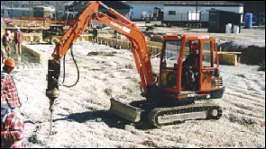 suspended from the boom of an excavator. The portable hydraulic devices or gearboxes have limited torque output and are used for the lower working load, say 10 to 20 tons. The picture at the right show a typical installing rig - in this case, a mini-excavator with a small drive head.
Install Torque, Why and What
There are several components to the resistance of the helical foundation passage through the soil. First, on the bottom of the leading part, or “lead”, of the foundation there typically is a section of the shaft protruding below the helical plate that is popularly called the “pilot point”. This point is typically cut to a slash point at a 45 degree angle or a double cut to a symmetrical point used to locate the lead at the earth’s surface.
The second and most significant contribution is due to the plate, which has two components, the leading edge and the flat bearing surfaces. First, the leading edge may be sharpened or flat, either makes little difference to the torque. The upper and lower bearing surfaces are in intimate contact with the soil and develop a resistance to the plate passing through the soil. In the case of sand, this resistance arises from the friction associated with that particular grain size, angularity, water content and density. Simply put it measures the in-situ direct shear strength of the soil. In the case of clay, the shear strength is a function of adhesion, having an upper limit of the undrained shear strength of the clay.
The shaft of the foundation also contributes to the torque required to install the helical foundation. Round tubular shafts present a large surface for the soil to shear against. Square bars on the other hand only abrade at the corners and therefore have a very small affect on the installing torque.
Friction Components
It is intuitive that the work or energy required to install the helical plate into the bearing stratum is related somehow to the capacity of the helical foundation. That is to say the strength of the soil is related to the effort required to install the helical plate. The simple relationship developed by the A. B. Chance Company in the late 1960’s as the basis of their shear pin torque indicator (or limiter) is still widely used today. That relationship is express as follows:
Qu = KT* T
Where Qu is the ultimate capacity in pounds, K is a constant with the dimensions of feet to the minus one power to get the units to work out, and T is installation torque in foot pounds. There has been a significant amount of data in the last 40 years that validates this expression. See the references cited at the end of this paper give this research.
Torque Relationships
The torque constant, KT has the default value of 10 for square shaft piles and 7 for the small diameter round shafts and as low as 5 for the larger diameter pipe shaft. Therefore the KT is a function of soil and the foundation’s configuration. Assuming a particular foundation configuration is constant, the Kt tends to be constant over the site. The default value may be used as it was develop as a guide but since it is very conservative the installer may be installing more foundation than necessary to handle the loads imposed. It is prudent to perform a load test to determine the capacity of the helical foundation and develop a site specific Kt for production control.
Static Loads
The loads determined using the torque relationship and load tests are for static loads. Impact and transient loads affect sand immediately as the excess pore pressure can be drained away in the time the load is on the bearing material. Clay bearing stratum, on the other hand will not be affected unless the load is so great as to cause a local punching failure or cavity expansion under the plate.
The full scale load test is a test of the static capacity of the helical foundation. The quick load test method more nearly approximates the in service loading of piles in general and is favored by this writer. Testing to two times the combined dead plus live load is typically used as the static load test but the use of load factors applied to the live and dead load is becoming more common.
Battered Piles
Some designers reduce capacity for battered foundations. The axial capacity of the helical foundation is unaffected by battering the foundation.
Long Term Behavior
The site specific KT determined from load tests may be used as production control. The long term capacity may then be determined directly in sand and other fast draining soils. Long term behavior in clay and the slow draining soils theoretically should be different because the cohesion over time goes to zero and a low value of phi angle is used for the long term capacity calculations. The long term capacity according to this calculation could be greatly reduced from the initial capacity. Actual results do not bear out the long term determination based on this method of calculation.
Two tests come to mind that that could be considered a subject for further research. About 30 years ago Chance conducted an unpublished long term test for their internal research in normally consolidated clay. The test was conducted using cyclical loads applied hydraulically for a period of nearly a year on multiple anchors. The effects of strain softening were the main concern but the results were surprising. The one square foot plates were first tested to the ultimate quick capacity as a control point. The plate where then loaded incrementally to failure with each increment being held for one month and then unloaded to zero and allowed to sit for a week and then reloaded to the next increment. The ultimate capacity when tested in this manner was on the order of 10% higher than the ultimate capacity determined by the quick method.
The second test was conducted by Northern States Power on transmission tower guy anchors that had been in service as at angle structures, hence subjected to long term loads for over ten years. Their test indicated the capacity had reduced approximately 10% which was much less than anticipated by the long term capacity calculation using the drained phi angle.
KT Values
The constant KT was originally developed from empirical data from tension tests of guy anchors for the electric utility industry. The criteria used to define the ultimate capacity in those early tests were not rigorous or even consistent. However, the valve of KT was derived as the lower limit of a scattering of data from quick tension tests in numerous locations and soil types throughout the United States. As stated above, this concept was the basis of the torque indicator that was actually developed as a torque limiter to prevent damage to the then recently developed helical anchor. However, this method of protecting the anchor from being over-torqued and damaged became a reasonably good method of production control.
Torque Measuring Disadvantages
There are several disadvantages to using installation torque as a method designing helical products. First and foremost, until the installation work is done, the torque constant is not definitively known and is therefore hard to design using an unknown. A load test at the outset can overcome this shortcoming and identifies the site specific torque constant KT. Further, in use the operator has to use care and skill.
Research Behind the Theory
There has been a great deal of proprietary research by the industry to quantify and predict the required installing torque required to install a helical foundation. There have been two other published reports by Hoyt, et al and Clemence, et al that propose methods that seem to give adequate results in the soil profile in which they were developed. The accurate measurement of the soil parameters is certainly one of the problems associated with the problem of predicting installing torque. Better measurement of the soil parameters will help the study of this relationship.
Torque Indicators
The patented shear pin “torque indicator” mentioned above is actually an in-line torque limiter developed originally to protect the wrench driven PISA family of anchors used in the electric utility industry. It is a torque limiting device that uses a number of shear pins to prevent the two machined shear plate halves from rotating independently. When the pins do shear it interrupts the installation effort applied to the helical anchor, preventing torsion damage to the anchor.
The next generation of the torque indication was a pair of foot long arms also installed directly in the drive line of the tooling that compressed a hydraulic load cell that read out in on a calibrated analog gage. That was an accurate system but liability issues caused them to be 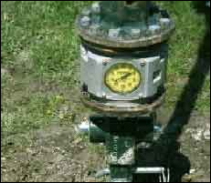 recalled. Slip ring transducer type load cell read out on an electronic bridge and various electronic devices had been tried with limited success. The only torque indicator marketed today that is traceable to the US Bureau of Standards is the mechanical device that has an enclosed torsion bar and an analog read out as shown in picture at the right. It is not rugged enough to be used on inclined installations such as tiebacks, but is often used to check other torque measuring devices.
The simplest and probably most often used is observing the twist in the shaft. This method is not very accurate as the material varies from supplier to supplier.
Presently there is a patented hydraulic differential pressure indicator that measures the pressure drop across the drive motor from which one can determine the torque output of the drive head. This has been the most rugged and accurate torque indicator to date.
Installing Torque Too Great
There are situations that arise when the torque required to install the helical pier is greater than the shaft’s ability to withstand or the drive motor will develop. There are several things the field personnel can do to work around that problem. First, reduce the rotational speed and down pressure and continue slowly. Secondly, reduce the number of helices or trim them down to a smaller size. It is logical that if the soil is so hard as to prevent the helices penetrating into the bearing strata, a smaller helix came be used to support the given load requirements. The capacity can be verified by tests.
Recall that the default value of KT is 10 but that it is site specific and may vary from 5 to 20. If the designer estimates the torque required to install the pier using the default value of 10, it will generally be correct but conservative. It may require less installing torque than estimated by this presumptive method.
Special Inspection
Many installations require special inspection of the installation of the pier. The inspector should be aware that the pier installation may have errors in torque readings due to obstructions causing temporary spike in the readings. The final torque is the average of the last three feet or often the last three readings. Another potential problem the inspector should be prepared for is “spin out” where the pier stops advancing and the torque goes to near zero due to rotating on top of an obstruction. Spinning without advancing disturbs the soil more than usual and the capacity may be significantly reduced. Also, speed of rotation should be constant to obtain consistent, meaningful indication of capacity.
General Notes and Observations:
If one assumes a given helix configuration and the given installation energy is constant, i.e. the installing machine remains constant then certain truisms follow:
Small diameter or displacement shafts disturb less soil than large diameter or displacement shafts.
Small displacement shafts result in lower pore pressure build-up than large displacement shafts.
Small displacement shafts will penetrate farther into a given bearing strata than large displacement shafts.
Small displacement shafts will penetrate soils with higher SPT “N” values than large displacement shafts.
Coarse angular saturated sand gives rise to very high Kt values e.g. Kt = 20+ (as opposed the default value of Kt = 10).
Moderately over-consolidated clays (OCR 3-4) yield Kt = 12-14 while normally consolidated clay gives Kt = 10-12 and highly sensitive clays (S = 10+) the torque verses capacity may not applicable.
Pulldown® Micropiles and large diameter shafts are special cases to the above torsion verses capacity discussion.
Finally, there is little that can substitute for local experience when subsurface construction is done. Additionally, according to Terzaghi, one should always have a “backup procedure” or another possible solution in the back of one’s mind when unexpected conditions are encountered because they will occur.
REFERENCES
A. B. Chance Company, Helical Screw Foundation – Design Manual for New Construction, Copyright 2003 Chance / Hubbell, 210 North Allen St., Centralia, MO 65240
Clemence, S.P., Crouch, L.K., and Stephenson, R.W. (1994) “Prediction of Uplift Capacity for Helical Anchors in Sand”, Proceedings of the 2nd Geotechnical Engineering Conference Cairo Egypt
Hoyt, R. M. and Clemence, S. P. (1989), “Uplift Capacity of Helical Anchors in Soil”, Proceedings of the 12th International Conference on Soil Mechanics and Foundation Engineering, Rio de Janeiro, Brazil.
Seider, G.L., Clemence, S.P. and Thorsten, R.E.(2003), “Helical Piles with Grouted Shafts-A Practical Overview”, Proceedings of the DFI 28th Annual Conference on Deep Foundations, Miami Beach, FL, pg. 221-231.
Vickars, R.A. and Clemence, S.P., (2000), “Performance of Helical Piles with Grouted Shafts,” Proc. New Technological Developments in Deep Foundations, ASCE GSP 100, Denver CO. 327-341
Photos courteous of Chance/Hubbell, Centralia, Missouri
Presented at the Deep Foundation Institute Specialty Conference on Helical Foundations and Tiebacks, Los Angles, CA. November 18, 2005