Copyright © 2011-26 Helical Pile World, LLC. All Rights Reserved.
Home | Engineers | Manufacturers | Installation Contractors | News | Contact Us


What is Shaft Buckling? Causes, Problems, and Prevention.

by ECP Engineer Garrett Roberts
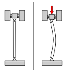
When a column of any type experiences axial compressive loading, it is susceptible to a failure mode known as buckling. Buckling is defined as the sudden and uncontrollable lateral deflection or bending of a column under an axial compressive load. It occurs when the load on the column exceeds a certain limit, called the critical buckling load, causing the column to deform laterally instead of remaining straight.
When a column, or any other vertical structural member that provides support to a structure, buckles, it loses its ability to provide it’s intended support and becomes laterally unstable. The resulting loss of structural support can potentially result in failure of the entire structure. In the case of helical piles, failure can cause the foundation to settle, leading to uneven floors, cracks along the wall’s floors and ceilings, basement flooding, decrease in property value, and in extreme cases, structural instability, and collapsing walls or floors.
Specifically talking about deep foundation helical piers, buckling poses a concern when there is a lack of sufficient lateral bracing from the surrounding soil. The soil is considered to brace the pile against buckling, but in order to provide sufficient lateral support, the soil must meet a minimum strength requirement. If a soil layer is thicker than five feet and contains standard penetration test blow counts less than 5, the structural member is considered unbraced, and is at risk of buckling.
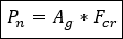
To determine if a helical member will buckle under such conditions, the engineering department at Earth Contact Products calculates the critical buckling load using the AISC design method, represented by the following expression:
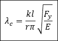
Where Pn is the critical buckling load, Ag is the cross-sectional area of the pile shaft, and Fcr is the critical buckling stress. Critical buckling stress is dependent on the slenderness of the column. Column slenderness is represented by the Greek symbol lambda sub c (λc) and is calculated with the following equation:
Where lambda sub c is column slenderness, k is the effective length factor, l is the maximum length of the column without sufficient lateral bracing, r is the radius of gyration about the axis of buckling, F sub y is the yield strength of the steel tube, and E is Young’s modulus of elasticity for steel.
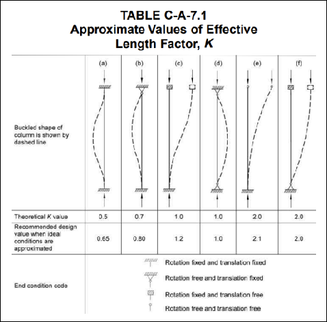
K, or the effective length factor, is dependent upon the end conditions of the pile. Deep foundation helical piles are typically classified as having pinned-fixed end conditions, and therefore have a design K value of 0.8. The AISC table of approximate values of Effective Length Factors for different end conditions is shown below.
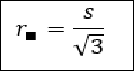
Earth Contact Products’ deep foundation helical piles are comprised of either round corner square bars or hollow tubes. The radius of gyration depends on the geometry of the shaft. The radius of gyration for round corner square bar columns is:
Where s is the length of the side of the square.
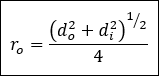
The radius of gyration for a hollow tube is:
Where do and di are the outer diameter and inner diameter respectively.
The yield strength of steel will vary depending on the quality of the steel used, but Earth contact products uses American steel, with a yield strength of 50 ksi. Youngs Modulus of Elasticity, E, is also a constant property of the material, equal to 29,000 ksi.
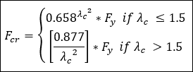
After obtaining all these values, plug them back into the equation for and solve for column slenderness. Once found, column slenderness can be used to solve for the critical buckling stress with the following piecewise function:
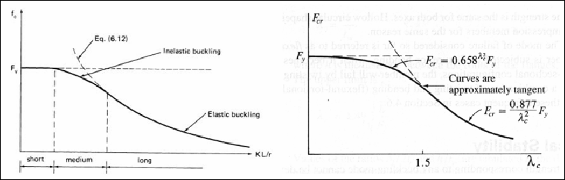
The function behaves differently depending on the slenderness ratio because different styles of columns buckle differently. Short columns do not buckle and simply fail because of the material yielding. Long columns typically fail by elastic buckling, but in-between these short and long failure modes the failure of the column occurs via inelastic buckling. The following figures show this distinction represented by the piecewise function.
After finding the critical buckling stress, all that is left is to multiply it by the cross-sectional area of the pile. The product will be the critical buckling load. This is the weight that will cause the support column to fail.
Now compare the critical buckling load to the ultimate load of the building. If the critical buckling load is greater than the ultimate load, then congrats, your helical pile is not at risk of buckling. However, if the critical buckling load is less than the ultimate load dictated by the site, then it is at risk of failure.
The most opportune time to notice that the piles will buckle is in the planning stage. While the project is still in development, calculating the critical buckling load can save you a lot of hassle down the road. The most common solution at this stage in development is to increase the size of the pipe and recalculate. As a purely hypothetical example, a project may have an ultimate load of 20 kips, and the critical buckling stress of 2-7/8” tube could be 18 kips, while the critical buckling stress of 3-1/2” tube may be 25 kips. In this example, the 2-7/8” tube would buckle, and therefore should not be used for the project whereas the 3-1/2” tube would be just fine to use.
As previously stated, it is easiest to address buckling early in development. “But what if I already ordered and received my piers from Earth Contact Products?” In rare cases, it is possible to reduce the ultimate load applied to each individual deep foundation helical pier by reducing the space between the piers, therefore mitigating the ultimate load. As another purely hypothetical example, a project may have an ultimate load of 30 kips with piers spaced 6 feet apart, and the critical buckling load is calculated to be 25 kips. The ultimate load of 30 kips in this example is equivalent to 5000 pounds per linear foot. Changing the spacing on this project from 6 feet to 4 makes the ultimate load 20 kips and is therefore not at risk of buckling. It is important to remember that helical piles have a minimum installation spacing requirement. To fully develop the helices, piers cannot be closer than three times the diameter of the largest helical (measured center to center).
If such spacing requirements cannot be overcome, it is best practice to use a larger diameter pier to overcome the buckling threat. Retrofitted ECP deep foundation helical piers can be removed and reused on other projects, assuming they have not buckled.
To conclude, shaft buckling is a serious concern for foundations in weak soils. To save yourself from massive headaches down the line, solve for the critical buckling stress before installing piers in weak soil, and adjust accordingly.
For more information on buckling, check out Manual of Steel Construction, Load & Resistance Factor Design, 3rd Edition, AISC, Inc., 2001.